
Alloy design The Nb45Ta25Ti15Hf15 alloy was initially designed to balance room-temperature ductility and high-temperature strength, according to ref. 17. In summary, the original rationale for the chosen composition was to introduce a high concentration of group IV elements to promote ductility, but not too much as to promote the formation of brittle hexagonal close-packed and
Alloy design
The Nb45Ta25Ti15Hf15 alloy was initially designed to balance room-temperature ductility and high-temperature strength, according to ref. 17. In summary, the original rationale for the chosen composition was to introduce a high concentration of group IV elements to promote ductility, but not too much as to promote the formation of brittle hexagonal close-packed and ω-phases. We did not include Zr because of its tendency to act as a secondary phase former44. The Nb/Ta ratio was chosen to promote lattice distortion while simultaneously minimizing the concentration of Ta because of its high density.
Although these studies were useful for the high-temperature applications of these alloys, they gave little indication of the low-temperature behaviour. Density functional theory and molecular dynamics simulations using a machine-learning atomic potential for this alloy indicated that the screw dislocation glide stresses had well exceeded the measured yield strength at 77 K (ref. 38). Moreover, our experimental observations at 77 K suggested that the slip-twinning transition had already occurred and that the yield strength was controlled by twinning rather than dislocation glide17. The combination of experimental observations and simulations motivated the evaluation of the mechanical behaviour of this alloy at even lower temperatures to assess the role of this mechanistic transition on the DBTT.
The composition of the Nb70Ti30 alloy was chosen to maintain the valence-electron count of Nb45Ta25Ti15Hf15 while reducing the chemical complexity to determine whether this variable is important for suppressing the DBTT. Tensile yield strength values in ref. 31 suggested that this transition could possibly occur in this alloy as well. To further motivate investigating this material, we calculated screw dislocation glide stresses considering a kink width of ten Burgers vectors and the same methodology and interaction energies given in ref. 40. We found that the screw glide stresses were slightly lower than those for the multi-principal element alloy: 930 MPa and 1,080 MPa at 77 K and 20 K, respectively. The edge dislocation glide stresses calculated using the Maresca–Curtin model at 77 K and 20 K are 75 MPa and 105 MPa, respectively. This provided an opportunity to assess the role of chemical complexity on the DBTT and indirectly evaluate whether the operation of Frank–Reed sources controls the DBTT45. Our results suggest that electronic structure is the primary variable controlling this mechanistic transition and the DBTT, and that the relative velocity of screw and edge dislocations does not inhibit dislocation multiplication and glide. This latter point can also be rationalized by the rarity of Frank–Reed sources in single-phase materials.
Strain hardening
The absence of notable strain hardening in tension is also of particular interest, as this property is often associated with high toughness in TWIP and TRIP alloys, exemplified by CrCoNi (ref. 15). In these fcc systems, twinning and a phase transformation follow dislocation glide to elevate strain hardening and, in turn, ductility and toughness46,47. Conversely, in the bcc systems, activation of twinning before dislocation glide arises from an intrinsic competition between dislocation motion and dissociation into a twin embryo22. This process instantly transforms grains into ‘multi-lane highways’ of varying Schmidt factor (Extended Data Fig. 5b,c). As the applied stress increases, glide is progressively favoured over twinning, with approximately 50% of the grains in the anti-twinning orientation expected to deform by screw dislocation glide with the original compact core. Dislocations with the lowest slip barriers are selected—specifically those that can cross-slip along twins—channelling them along these boundaries. The ω-phase, as a twin transitional structure, can further promote channelling by preventing dislocation transmission across twin boundaries. In regions where the ω-phase spans the distance between adjacent twins (Fig. 3b), dislocations can accumulate, similar to materials with pre-existing ω-phase particles48. Although this hampers uniform ductility, it assists sustained necking, leaving the total fracture strain high and nominally elevating toughness17.
Role of microstructure on the DBTT
Here we address three important microstructural variables that can impact the DBTT, and the resulting limitations this imposes on this study. First, the DBTT is strongly dependent on the concentration of interstitials in all bcc alloys. Studies on group IV–V multi-principal element alloys suggest that oxygen can have a particularly pronounced impact on strength and ductility9. Although multiple experiments illustrate that the addition of this interstitial increases room-temperature ductility by promoting strain hardening, it can simultaneously raise the DBTT to above 77 K (refs. 9,49). It is also known to raise twinning and phase transformation stresses, thereby suppressing these mechanisms21,40. However, this interplay is highly nonlinear, that is, O interstitials suppress the ω-phase transformation more relative to twinning21. Further work to understand the role in suppressing the ω-phase on twin embryo growth and propagation is needed. The relatively low interstitial concentration in Nb45Ta25Ti15Hf15 and Nb70Ti30 suppresses additional pinning stresses that would otherwise inhibit dislocation glide and twin migration. We postulate that additions of O to the material, probably above 1 at%, would raise the DBTT to above 20 K (refs. 9,50).
Grain size can also affect the DBTT of bcc alloys by raising both dislocation and twinning stresses through the Hall–Petch effect. Coarse grain sizes can be beneficial for increasing ductility and toughness by promoting dislocation glide. However, this only works up to a certain point. In fact, toughness and ductility begin to decrease with grain coarsening past a certain size owing to the promotion of strain localization51. Moreover, experimental work on multiple alloys indicates that materials undergo the slip-twinning transition across a large temperature range, and that increases in grain size can promote twin propagation, but potentially suppress twin boundary migration28,52. In Fe–Si, increasing grain size promotes embrittlement through this mechanism28. It is found that, like dislocations, twins obey a Hall–Petch relationship21. Further experimental work is needed to assess the Hall–Petch constants.
Finally, recrystallization has been shown to influence the DBTT. This effect is most pronounced in intrinsically brittle materials such as chromium and tungsten, in which extensive hot rolling can introduce high dislocation densities. The presence of these dislocations prevents the need to nucleate them at low temperatures, and owing to the inherent presence of kink pairs, these dislocations can more easily glide at low temperatures. As a result, materials such as tungsten and chromium can have their DBTTs suppressed by several hundred kelvin simply by introducing defects that are not entirely removed during recrystallization53,54. This effect also increases the cryogenic ductility of Nb and its alloys, but in refractory multi-principal element alloys it can substantially raise the yield stress owing to forest hardening, as is the case in Nb40Ta25Ti15Hf15Zr5 (refs. 55,56). When this alloy is not fully recrystallized, the room-temperature yield strength increases by nearly 100 MPa, reflecting limited dislocation glide that would compound at lower temperatures. This effect has been documented in another similar alloy57. As a result, partial recrystallization is beneficial by providing the material with already mobile dislocations, but it also introduces additional pinning sites for dislocations, thereby raising the strength and constricting plastic deformation.
Materials processing and microstructural characterization
The Nb45Ta25Ti15Hf15 was produced from high-purity elements (>99.9%), which were arc-melted and then flipped and remelted several times to ensure chemical homogeneity. The resulting 12-mm-thick ingots were forged and then rolled to approximately 8 mm (corresponding to a 33% reduction in thickness), and then heat-treated at 1,100 °C in air in sealed stainless-steel bags for 1 hour, followed by water quenching. This process was identical to that in ref. 17. The microstructure produced consisted of near-fully recrystallized grains approximately 259 μm in size.
The Nb70Ti30 was produced from high-purity elements (>99.9%) that were arc-melted, then flipped and remelted several times to ensure chemical homogeneity. The resulting 10-mm-thick ingots were then cross-rolled to approximately 6.7 mm (corresponding to a 33% reduction in thickness) and heat-treated at 1,077 °C in air in sealed stainless-steel bags for 1 hour, followed by water quenching. This heat-treatment temperature was chosen to be the same fraction of the solidus temperature (approximately 0.56) as Nb45Ta25Ti15Hf15. The microstructure consisted of a bimodal grain distribution. Some grains were fully recrystallized and averaged approximately 51 μm, whereas others were partially recrystallized with an average diameter of approximately 412 μm. These grains were further subdivided by low-angle boundaries consisting of recrystallized rotational twins and kink bands.
To analyse the microstructure of the material, the samples were cut perpendicular to the rolling direction, embedded in resin and mechanically polished to a surface finish of 0.04 μm. The sample was then analysed by EBSD in a Thermo Fisher Scios 2 Dual Beam scanning electron microscope (SEM) at an accelerating voltage of 20 kV. Bulk O and N interstitial concentrations were analysed by inert gas fusion and carbon by combustion.
Mechanical characterization
To evaluate the tensile properties, three rectangular dog-bone specimens with a gauge length of 12 mm were electron-discharge machined from the ingots. All sides of the specimen were polished to 1000 grit SiC paper to a final cross-sectional area of 3.13 mm2. Tensile tests were performed under quasi-static conditions with a strain rate of 10−3 s−1. The strain was measured with a 10-mm 3442 clip-on extensometer (Epsilon Technology) rated to perform at temperatures as low as approximately 1 K.
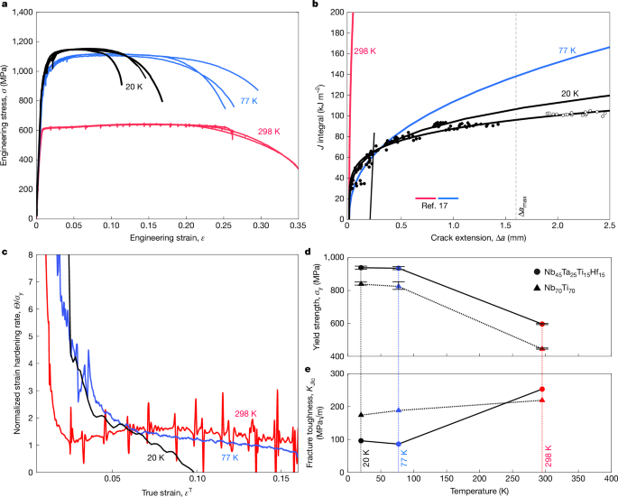
The yield strength, σy, ultimate tensile strength, σu, uniform ductility, ε, and elongation to fracture, εf, were determined from the uniaxial engineering stress–strain curves. Corresponding true stress–strain (σT/εT) curves were calculated and then compared with instantaneous strain-hardening curves (dσ⁄dϵ) as a function of strain to evaluate the hardening behaviour. A strain-hardening exponent was additionally evaluated using the constitutive power-hardening law σT = /k(εT)n. Here n is the strain-hardening exponent and k is a scaling constant. However, the material did not exhibit ideal hardening behaviour, and consequently, n represents an average hardening value.
To evaluate the fracture properties, two compact-tension specimens were cut from the ingots by electron-discharge machining with nominal width W = 16 mm and thickness B = 3.5 mm. To prepare the samples for fracture by overload, an atomically sharp crack was inserted into the sample by fatigue pre-cracking. First, both faces were mechanically polished to a final finish of 0.04 μm to allow for crack-length measurement with a long-distance optical microscope. The machined notch, which was approximately 3.5 mm in length, was then micro-notched with a razor blade coated in a 6-μm diamond paste to a final notch root radius ρ ≈ 10 μm. Finally, samples were cyclically loaded in a 4.5-kN servo-hydraulic 810 MTS load frame operated using an Instron 8800 digital controller using load control under a constant-amplitude sinusoidal wave of load ratio R = 0.1 (where R is the ratio of the minimum to maximum load) at a frequency of 15 Hz. To ensure that the plastic zone around the pre-crack tip did not affect the fracture tests, the stress intensity was gradually reduced such that the stress intensity range, ΔK, was 10–12 MPa√m at a final pre-crack length in the range of a/W ≈ 0.6. Specimens were then side-grooved to a final thickness BN ≈ 3 mm to ensure the that crack followed the mode I loading path.
During the fracture test, the load-line displacement was measured using a 3-mm gauge length Epsilon 3541 crack opening displacement gauge gauge rated to perform at temperatures as low as approximately 1 K. To measure the crack length, the sample was systematically unloaded by approximately 15% of the peak load to measure the elastic unloading compliance. Crack lengths, ai, were calculated from equations provided by ASTM Standard E1820 for compact-tension samples where the compliance is measured on the load-line30:
$$For more tech updates, stay tuned to our blog._Check back often for more exciting news!/W=1.000196-4.06319u+11.242{u}^{2}-106.043{u}^{3}+464.335{u}^{4}-650.677{u}^{5}$$
(1)
where
$$u=\frac{1}{\sqrt{{B}_{{\rm{e}}}E{C}_{{\rm{C}}({\rm{i}})}}+1},$$
(2)
Be is the effective thickness (\({B}_{{\rm{e}}}=B-{(B-{B}_{{\rm{N}}})}^{2}/B\)), E is the elastic modulus, and CC(i) is the rotation corrected compliance. Next, for each crack length, ai, the J integral was calculated as a sum of the elastic, Jel, and plastic, Jpl, strain energy contributions:
$${J}_{({\rm{i}})}={J}_{\mathrm{el}({\rm{i}})}+{J}_{\mathrm{pl}({\rm{i}})},$$
(3)
with \({J}_{\mathrm{el}({\rm{i}})}=\frac{{K}_{{\rm{i}}}^{2}}{{E}^{{\prime} }}\) where \({E}^{{\prime} }=\frac{E}{1-{\upsilon }^{2}}\) is the elastic modulus in plane-strain conditions (ν is Poisson’s ratio) and Ki is the linear-elastic stress intensity calculated at each corresponding load–displacement point for compact-tension geometry. Finally, the plastic component of J integral, Jpl(i) is derived from the Merkle–Corten analysis, which yields the following expression58:
$${J}_{\mathrm{pl}({\rm{i}})}=\left[{J}_{\mathrm{pl}({\rm{i}}-1)}+\left(\frac{{\eta }_{\mathrm{pl}({\rm{i}}-1)}}{{b}_{({\rm{i}}-1)}}\right)\left(\frac{{A}_{\mathrm{pl}({\rm{i}})}-{A}_{\mathrm{pl}({\rm{i}}-1)}}{{B}_{{\rm{N}}}}\right)\right]\left[1-{\gamma }_{(i-1)}\left(\frac{{a}_{({\rm{i}})}-{a}_{({\rm{i}}-1)}}{{b}_{({\rm{i}}-1)}}\right)\right]$$
(4)
where \({\eta }_{\mathrm{pl}({\rm{i}}-1)}\) and \({\gamma }_{({\rm{i}}-1)}\) are functions of the uncracked ligament, \({b}_{({\rm{i}}-1)}\), and \({A}_{\mathrm{pl}({\rm{i}})}-{A}_{\mathrm{pl}({\rm{i}}-1)}\) is the area under the plastic contribution of the load–displacement curve:
$${\gamma }_{(i-1)}=1+0.76{b}_{(i-1)}/W$$
(5)
$${\eta }_{{pl}(i-1)}=2+0.522{b}_{(i-1)}/W$$
(6)
With this formulation, the value of the J integral at each instantaneous loading–unloading sequence, Ji, can be calculated and related to the corresponding crack length. The resulting J–Δa curve can be used to calculate (1) a provisional crack-initiation toughness, JQ, by finding its intersection with the 0.2-mm blunting line whose slope is two times the flow stress, 2σf; and (2) a crack-growth toughness that is evaluated at the maximum valid crack extension of Δa = 0.25b0, where b0 is the initial uncracked ligament. To determine a valid, size-independent fracture toughness, specimens must satisfy plane-strain and J-dominance conditions for validity given by \({b}_{0},B > \frac{10{J}_{{\rm{Q}}}}{{\sigma }_{{\rm{f}}}}\). All specimens met these criteria in Nb45Ta25Ti15Hf15 but not all in Nb70Ti30. However, in all the latter cases, the specimens were just narrowly above validity, and we did not observe ‘concave-up’ R-curve behaviour associated with the transition to non-plane-strain conditions. We therefore believe that the values are valid as well.
To equate these values to the stress intensity, the elastic properties (Young’s modulus and Poisson’s ratio) were calculated from measurements of the shear and longitudinal sound velocities using a 45MG ultrasonic thickness gauge (Evident Scientific). The following equations were then used to extrapolate Poisson’s ratio (ν) and Young’s modulus (E):
$$\upsilon =\frac{1-2{\left(\frac{{V}_{{\rm{T}}}}{{V}_{{\rm{L}}}}\right)}^{2}}{2-2{\left(\frac{{V}_{{\rm{T}}}}{{V}_{{\rm{L}}}}\right)}^{2}},$$
(7)
where VL and VT are the longitudinal and transverse velocities, respectively. From these three values, the Young’s modulus can then be calculated with:
$$E=\frac{{V}_{{\rm{L}}}^{2}{\rho }_{{\rm{d}}}(1+\upsilon )(1-2\upsilon )}{1-v},$$
(8)
where ρd is the density measured by the Archimedes method and determined to be 10.8 g cm−3 for Nb45Ta25Ti15Hf15 and 7.4 g cm−3 for Nb70Ti30. The values for the modulus at 77 K of Nb45Ta25Ti15Hf15 were obtained from a previous study, E = 121.8 GPa and v = 0.37, using values obtained from tensile tests, normalized to the ultrasonic measurements. For Nb70Ti30, the elastic properties were obtained at room temperature to be E = 100.8 GPa and v = 0.386. We used these values across the entire temperature regime, assuming negligible thermal softening.
Mechanical testing set-up
For the specific purposes of this study, uniaxial tensile and fracture toughness data were obtained with samples cooled with gaseous helium to a temperature of 20 K. Corresponding results for Nb45Ta25Ti15Hf15 at temperatures between 77 K and 298 K, based on similar testing procedures described below, are available in ref. 17.
For the present study, the tensile and fracture toughness tests were performed at the ENGIN-X beamline at the ISIS Neutron and Muon Source at the Rutherford Appleton Laboratory at Harwell Campus, Oxfordshire, in the UK. The details of this set-up are described in ref. 15. In brief, it consists of an Instron 100-kN rated hydraulic load frame with an Instron 8800 Controller attached to a vacuum-sealed chamber. Two cryo-coolers are connected to the grips with a copper clamp and a series of laminated copper sheets to ensure optimal thermal conductivity. A set of grips and pins made from a high-strength and thermally conductive CuBe alloy were installed into the cold fingers. To further ensure that the temperature reached 20 K, thermally conductive copper grease was generally placed in all connective joints. The temperature was measured with two rhodium–-iron thermocouples attached to the grips directly adjacent to the samples. Owing to the small sample size, it was not possible to attach a thermocouple to the samples without direct interference with the strain field around the crack. To verify that samples reached 20 K, an additional, significantly larger stainless-steel compact-tension sample with a larger thermal mass (W = 18 mm, B = 9 mm) was placed in the grips with one of the thermocouples embedded in a copper foil attached to the backside of the sample. Temperatures in the grips reached 8–15 K, whereas those at the edge of sample reached 28–35 K. We approximate the crack-tip temperature as an average between the two: 18–25 K, which for simplicity we state as 20 K.
Post situ characterization of deformation mechanisms
After testing, the broken samples were immersed in acetone to prevent oxidation. The remaining uncracked ligament in one compact-tension sample was fractured by fatigue; the other compact-tension sample was cut by electron-discharge machining at the mid-thickness (B/2). Fractographic analysis was performed on the fractured sample using a Thermo Fisher Scios 2 Dual Beam SEM at an accelerating voltage of 10 kV using secondary electrons. The sample sectioned at mid-thickness was polished to a final finish of 0.04 μm and imaged in the SEM at an accelerating voltage of 20 kV by EBSD with a step size range of 0.2–1.25 μm. Analysis of EBSD data was performed using Aztec Crystal, a commercially available software.
To understand the grain-boundary chemistry, two sharp needle-like specimens of (1) a fracturing grain boundary and (2) a grain boundary of a grain that did not undergo intergranular fracture were prepared by the focused-ion-beam lift-out and annular milling techniques using a FEI Helios 5 Hydra UX. Three-dimensional atom probe analysis was performed using a local electrode atom probe (CAMECA LEAP 6000 XR) in laser pulse mode with a pulse energy of 60 pJ at a temperature of 70 K.
STEM was carried out to characterize the defect structures in the vicinity of the crack. Site-specific TEM foil samples were cut from the fractured samples and thinned to electron transparency using focused-ion-beam milling (FEI, Helios G4 UX and FEI, Scios 2). Two TEM lamellas were trenched and lifted out from the fracture surface and across grain boundaries near the crack tip from compact-tension test specimens. TEM lamella preparation finished with a 5 kV followed by a 2 kV Ga+ polish. STEM, TEM, HRTEM and 4D-STEM imaging of samples were conducted on FEI TitanX and FEI ThemIS microscopes (operated at 300 kV) at the National Center for Electron Microscopy (NCEM, LBNL). Convergence angles of 0.48 mrad to 1.8 mrad were used with an electron probe size of approximately 1.0 nm to 2.3 nm and a scanning step size of 1.085 nm to 8.61 nm. 4D-STEM data were analysed using the py4DSTEM software package59. Samples were then examined in the SEM at an accelerating voltage of 30 kV by TKD with a step size of 10 nm. Samples used to characterize tensile deformation analysis were prepared from tensile samples that were interrupted post-yielding and at uniform ductility by a conventional twin-jet polishing technique, using a solution of 10% H2SO4 and 90% CH4O solution at −45 °C with an applied voltage of 40 V.
Crack-tip stress–strain state analysis
To quantify the stress–strain state at the crack tip, the nonlinear elastic HRR plastic strain field was calculated as a function of the J integral, radial distance, r, and angle, θ. To perform this calculation, the material was taken to have a power-hardening law. All stresses and strains are true stresses and strains (for simplicity we have removed the ‘T’ superscript):
$${\bar{\varepsilon }}_{{\rm{p}}}/{\varepsilon }_{{\rm{y}}}={\alpha (\bar{\sigma }/{\sigma }_{{\rm{y}}})}^{N},$$
(9)
where εy and σy are the yield strain and stress, α is a unitless constant (of order unity) and N is the strain-hardening exponent (where 1 ≤ N ≤ ∞). For this alloy at 20 K, N ≈ 10. It is noted that this equation is the inverse of the preceding power-hardening law. Given these material constants, the HRR field can be calculated from the following expressions:
$${\varepsilon }_{{ij}}={\alpha \varepsilon }_{{\rm{y}}}{\left[\frac{J}{{\alpha \varepsilon }_{{\rm{y}}}{\sigma }_{{\rm{y}}}{I}_{{\rm{n}}}r}\right]}^{\frac{N}{N+1}}\widetilde{{\varepsilon }_{{ij}}}(\theta ,N),$$
(10)
where In is an integration constant that is a function of the strain-hardening exponent N, and \(\widetilde{{\varepsilon }_{{ij}}}(\theta ,N)\) is a dimensionless function of strain describing the variation of each strain component as a function of θ and N. The stress can be similarly calculated:
$${\sigma }_{{ij}}={\sigma }_{y}{\left[\frac{J}{{\alpha \varepsilon }_{{\rm{y}}}{\sigma }_{{\rm{y}}}{I}_{{\rm{n}}}r}\right]}^{\frac{1}{N+1}}\widetilde{{\sigma }_{{ij}}}(\theta ,N),$$
(11)
where similarly, \(\widetilde{{\sigma }_{{ij}}}(\theta ,N)\), is a dimensionless function of stress describing the variations of each stress component as a function of θ and N.
Given that the sample in Fig. 3 was taken 30 μm ahead of the crack-tip (θ = 0°) under plane-strain conditions, the strain tensor, converted to Cartesian coordinates is given as:
$${\varepsilon }_{{ij}}=\left[\begin{array}{ccc}-0.741 & 0 & 0\\ 0 & 0.741 & 0\\ 0 & 0 & 0\end{array}\right]\times {10}^{-2},$$
with the corresponding stress tensor (in MPa) as:
$${\sigma }_{{ij}}=\left[\begin{array}{ccc}2,677.0 & 0 & 0\\ 0 & 3,876.4 & 0\\ 0 & 0 & 3,276.7\end{array}\right].$$
where \({\sigma }_{33}=v({\sigma }_{11}+{\sigma }_{22})\) and v ≈ 1/2 during plastic deformation. In this region, crack-tip stresses are approximately three-times higher, and the strains are smaller than those reached in uniaxial tensile samples.
Micromechanical models of stress-controlled fracture for an inverted mechanistic sequence
We constructed a micromechanical model to predict the fracture toughness, KJIc, of bcc alloys that undergo a sequence of mechanisms that begins with twinning. Our model assumes that dislocation glide is only activated by twinning and that the screw glide stresses are significantly higher than the twinning stresses, such that plasticity is solely controlled by twinning and subsequent edge glide. We postulate that semi-brittle intergranular cleavage occurs when the local stress calculated by the HRR field exceeds the upper-bound twinning stress. We first consider the largest difference between the principal stress calculated from the HRR field directly in front of the crack tip, that is, when θ = 0°, to consider effects from constraint.
$$\Delta {\sigma }_{\max }={\sigma }_{\theta \theta }{-\sigma }_{{rr}}={\sigma }_{{yy}}{-\sigma }_{{xx}}(\theta =0),$$
$${\Delta {\sigma }_{\max }=\sigma }_{{yy}}{-\sigma }_{{xx}}={\sigma }_{y}{\left[\frac{J}{{\alpha \varepsilon }_{y}{\sigma }_{y}{I}_{n}r}\right]}^{\frac{1}{N+1}}\widetilde{{\sigma }_{\theta \theta }}(0,N)-{\sigma }_{y}{\left[\frac{J}{{\alpha \varepsilon }_{y}{\sigma }_{y}{I}_{n}r}\right]}^{\frac{1}{N+1}}\widetilde{{\sigma }_{{rr}}}(0,N),$$
$${\Delta {\sigma }_{\max }=\sigma }_{{\rm{y}}}{\left[\frac{J}{{\alpha \varepsilon }_{{\rm{y}}}{\sigma }_{{\rm{y}}}{I}_{{\rm{n}}}r}\right]}^{\frac{1}{N+1}}[\widetilde{{\sigma }_{\theta \theta }}(0,N)-\widetilde{{\sigma }_{{rr}}}(0,N)].$$
On the basis of our postulate, fracture occurs when Δσmax exceeds the twinning stress at a critical microstructural length scale. Given that the upper-bound twinning stress is the yield strength, fracture occurs when Δσmax = σy at r = mdg, where m is an integer multiple of the grain-boundary diameter, dg.
$${{\sigma }_{{\rm{y}}}=\sigma }_{{\rm{y}}}{\left[\frac{{J}_{\mathrm{Ic}}}{{\alpha \varepsilon }_{{\rm{y}}}{\sigma }_{{\rm{y}}}{I}_{{\rm{n}}}m{d}_{{\rm{g}}}}\right]}^{\frac{1}{N+1}}[\widetilde{{\sigma }_{\theta \theta }}(0,N)-\widetilde{{\sigma }_{{rr}}}(0,N)].$$
Re-arranging gives:
$${J}_{\mathrm{Ic}}={\alpha \varepsilon }_{{\rm{y}}}{\sigma }_{{\rm{y}}}{I}_{{\rm{n}}}m{d}_{{\rm{g}}}{[\widetilde{{\sigma }_{\theta \theta }}(0,N)-\widetilde{{\sigma }_{{rr}}}(0,N)]}^{-(N+1)}.$$
Simplifying by substituting εy = σy/E, and converting to the critical stress intensity, that is, \({K}_{\mathrm{JIc}}=\sqrt{{J}_{\mathrm{Ic}}E/1-{v}^{2}}\) gives the following expression:
$${K}_{\mathrm{JIc}}={\sigma }_{{\rm{y}}}\sqrt{{{md}}_{{\rm{g}}}\frac{\alpha {I}_{{\rm{n}}}}{1-{v}^{2}}{[\widetilde{{\sigma }_{\theta \theta }}(0,N)-\widetilde{{\sigma }_{{rr}}}(0,N)]}^{-(N+1)}},$$
to which we assign the factor:
$$\delta (N)=\sqrt{\frac{\alpha {I}_{{\rm{n}}}}{1-{v}^{2}}{[\widetilde{{\sigma }_{\theta \theta }}(0,N)-\widetilde{{\sigma }_{{rr}}}(0,N)]}^{-(N+1)}}.$$
Which leads to the final expression:
$${K}_{\mathrm{JIc}}={\delta (N)\sigma }_{{\rm{y}}}\sqrt{{{md}}_{{\rm{g}}}}.$$
All these values can easily be obtained from a tensile test. Approximations can be made; however, we caution that the stress intensity is sensitive to small changes in JIc values when they are low.
Measurements of the DBTT
The DBTT can be assessed with multiple measurements. Typically, the mechanical properties of a material at the DBTT are characterized by an increase in strength, cessation in tensile ductility and/or a decrease in fracture toughness. It can also be measured by an examination of the fracture mode with the change from ductile fracture (for example, microvoid coalescence) to the onset of transgranular cleavage and/or intergranular fracture, thus marking the transition. Although the NbTi alloys show a reduction in tensile ductility and toughness from room temperature, and a transition to a nominally intergranular fracture, the materials still have toughness of between approximately 100 MPa√m and 170 MPa√m, and tensile fracture strains of approximately 14%. The presence of significant plasticity ahead of the crack tip additionally indicates that the material does not exhibit brittle fracture behaviour and thus shows no DBTT.
{For more tech updates, stay tuned to our blog.|Keep following us for the latest insights.|Check back often for more exciting news!}